Last year I was helping my daughter on her school STEM project. She chose the reverse engineering category and decided to take apart an old pump that we had. Everything was going great until we got to the electric motor. It was much more difficult to disassemble than either of us imagined. We ended up using a hack saw to cut the motor in half and then cut a cross section out of one of the parts. This didn’t give us a great view of the motor, but it did show us that instead of the simple DC motor that we were expecting, it was an AC induction motor.
To make sure that my daughter understood of how everything worked I thought it would be fun to get a small kit and have her build it so she could see all the parts. Unfortunately the only kits we could find were for DC motors. But we did find a few YouTube videos that showed how people built their own induction motors so we decided to follow their example and build one from scratch.
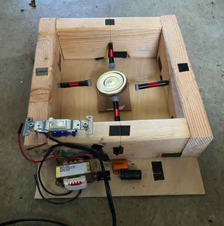
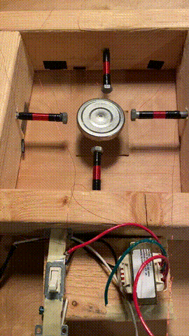
The finished product
Resources
The most important resource we found was the amazing AC Induction Motor YouTube video from 2009 by Christine Mecklenborg. The video contains a ton of information and Christine answers a lot of viewer questions in the comments. She also links to an AC Circuits text book that includes useful information about how to build a similar motor. Finally we watched a YouTube video from American Tech that shows the entire build of a similar induction motor including a quick flash of a schematic around the 4:41 mark.
Motivation
This post exists to collect all of the resources in a single place and to explain why choices were made. The explanation is important so that if a specific part that is unavailable then you should be able to figure out how to adapt the design. For instance in Christine’s video she uses a 220 μF capacitor but all I could find was a 100 μF one so I wanted to know what other changes I needed to make so that it would work.
Materials
Capacitor - 100 μF non-polarized
The purpose of the capacitor is to change the phase of one branch of the circuit so that all the electromagnets aren’t the same polarity at the same time. If they were then the rotor would never spin. The actual capacitance of the capacitor does not matter, so a 100 μF one works just as well as the 220 μF one. The capacitor also provides a little bit of impedance (impedance is like resistance but for an AC circuit) to the system reducing the amount of current flowing through the coils. Ohm’s law states \(V=IR\) so \(I=\frac{V}{R}\). With a constant voltage the current goes down as the resistance increases. You can calculate the impedance of a capacitor with the equation \(Z = \frac{1}{2\pi fC}\) where:
- \(Z\) is the impedance in ohms
- \(f\) is the frequency in Hz (60 in the US)
- \(C\) is the capacitance in farads.
For this build we are using a 100 μF capacitor, so the impedance is: \[Z = \frac{1}{2\pi(60)(100 * 10^{-6})} = \frac{1}{0.0377} = 26.5\Omega\]
You can also use a calculator to make your life easier.
A final note about the capacitor, it is very important that it is non-polarized (sometimes called a crossover capacitor). A polarized capacitor can fail (with a pop and the top will swell) if the current is flowing the wrong direction.
Resistor - 20 \(\Omega\) rated for 25 Watts
Just like the capacitor reduces the current one branch of the circuit, the resistor does the same thing for the other branch. To keep the current in the branches similar I selected a 25 \(\Omega\) resistor. You can buy lots of cheap resistors but you need to pay attention to the power rating for the one you select. To figure out the required rating you can use the power law. \[P = IV\] In our build we are using a 12V power supply, so \(V = 12\). The current, \(I\), can be calculated using Ohm’s law, \(I=\frac{V}{R}\). We end up with: \[P = \frac{V}{R}V = \frac{V^2}{R} = \frac{12^2}{25} = 5.76\] So as long as the resistor can handle at least 5.76 W then it should be fine. To be safe I bought a 25 W resistor which leaves a lot of room for error.
Warning, when running the resistor will get very hot. Be careful around it.
Transformer - 120 to 12 volt AC 2000 mA
The transformer is not necessary, the build will work on mains voltage, but that is more than I am comfortable working with, so I bought a 120 to 12 volt transformer with a 2000 mA maximum current. I just felt better working with less power.
At first I bought a 500 mA transformer, but it didn’t seem to have enough power to make the motor work, so I upgraded to 2000 mA.
Other items
- 32 AWG magnet wire
- This type of wire has a thin coating on it. You can remove the coating using some fine grained sandpaper on the wire.
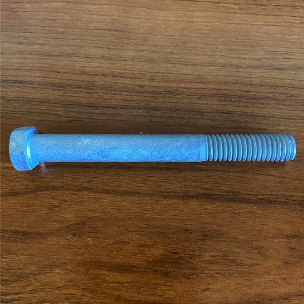
- 4 galvanized steel bolts
- The make of these bolts does not actually matter. For example the instructions from the AC circuits text book use cardboard tubes. I used galvanized steel bolts though.
- Rotor
- I used a lit from a jar of pasta sauce balanced on a nail so it can rotate freely.
- 2x4 boards for frame
- 2 prong replacement plug
- This is so that the transformer can be plugged into an outlet.
- Light switch
- To provide an easy way to turn the motor on and off.
Schematic
This is a parallel circuit where one branch contains a capacitor and the other contains a resistor. Notice that the rotor is not directly connected to the circuit.

Procedure
Create a wooden frame. I used a spare 2x4 that I cut up. You will want to make sure that the area in the center of the frame is just large enough for the bolts and your rotor. I also pre-drilled the holes for the bolts to make them easier to install later.
Wrap each bolt with 220 turns of the wire. Leave several inches of wire at both ends. I preferred using bolts where the threads do not cover the entire length of the bolt to make it easier to wrap the wires around them. If your bolt is threaded all the entire length you can write the threads in tape instead. I also wrap both ends in electrical tape to keep the wire from unwinding.
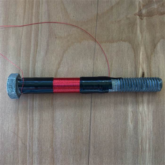
The bolt before and after wrapping it 220 times with the 32 AWG magnet wire.
- Once the four bolts are wrapped, mount them all in a frame so that the end of the bolts leave just enough room for the rotor in the middle.
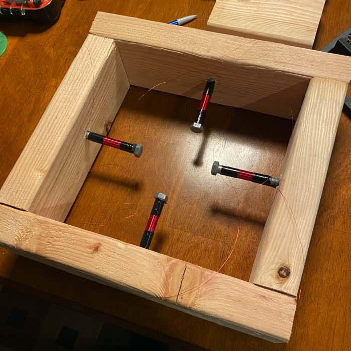
Wire wrapped bolts mounted in a wooden frame.
- Using the schematic as a guide connect the rest of the components. The wire from the bolts are connected to the ones directly across from them. Wire the capacitor in one branch and the resistor in the other. Connect everything to the transformer. Plug it in and turn it on. With any luck the rotor will slowly start to turn.
It really works!
I’m not an electrical engineer. I’ve pieced together these instructions from several online resources, so it is possible there are mistakes. If you notice any issues, please leave a comment and I’ll do my best to fix them.